This workflow directly attacks the cost of scrap and rework by moving from reactive defect detection to predictive process correction. When a vision model detects a pattern of dimensional drift or surface anomalies indicating tool wear, it triggers an automated calibration sequence. The operational upside comes from preventing entire batches of non-conforming product, reducing unplanned downtime, and extending mean time between failures (MTBF). Implementation requires integrating edge vision analytics with machine PLCs or APIs and a CMMS like SAP PM or Fiix for work order generation.

Automation
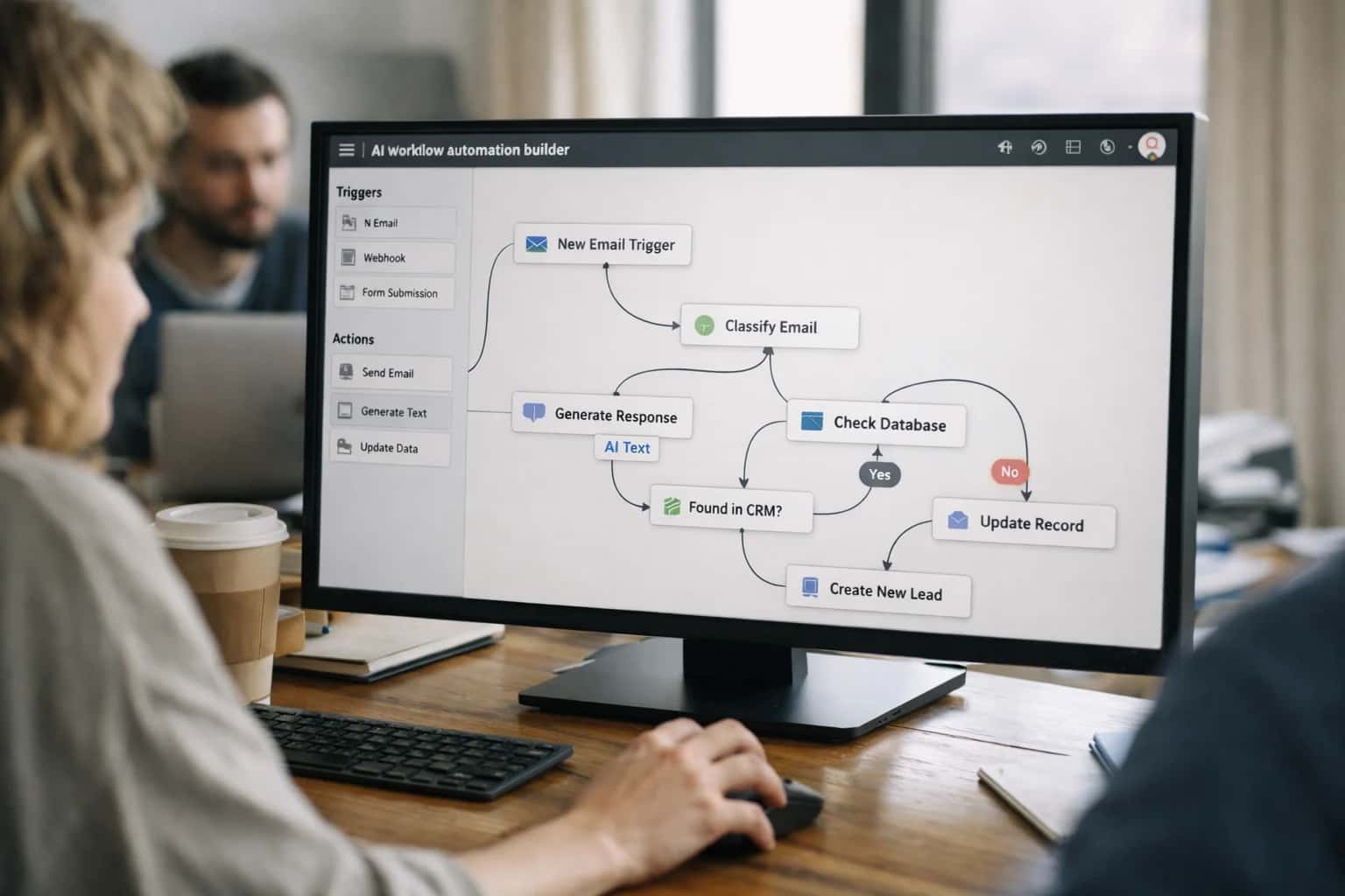
Automation Workflow for Triggering Machine Calibration from Vision System Alerts
A custom predictive maintenance workflow that connects vision analytics to machine APIs and CMMS systems, automatically generating calibrated adjustment commands or maintenance work orders to prevent defect batches before tolerance limits are breached.
AUTOMATION ARCHITECTURE
Implementing Predictive Machine Calibration from Vision System Alerts
This page details a custom automation workflow that triggers machine calibration from vision system alerts, preventing defect batches by correcting equipment before tolerance limits are breached.
The architecture hinges on a central orchestrator, built with frameworks like LangGraph, that evaluates the alert's severity against historical calibration data and predefined business rules. If the drift is within a safe, programmable threshold, it sends direct adjustment commands via the machine's API or industrial protocols like OPC UA. For more significant deviations, it creates a prioritized work order in the CMMS, routing it to the appropriate maintenance team with all contextual data. Critical controls include confidence scoring on the vision alert, mandatory human-in-the-loop approval for major interventions, and a closed-loop verification step where post-calibration inspection data confirms the correction's effectiveness.
AUTOMATION WORKFLOW FOR TRIGGERING MACHINE CALIBRATION FROM VISION SYSTEM ALERTS
Business Impact: From Scrap Cost to Prevented Loss
This workflow prevents defect batches by connecting vision analytics directly to machine control systems, automatically triggering calibrated adjustments before tool wear breaches tolerance limits.
01
Direct Scrap Cost Reduction
By detecting process drift (e.g., tool wear, misalignment) from vision data and triggering calibration before out-of-spec parts are produced, this workflow directly reduces material waste. It converts reactive scrap—entire batches of defective product—into a small number of calibration samples, protecting margin on high-value components.
15-30%
Scrap Reduction
Hours
vs. Batch Detection
02
Uptime Protection & Throughput Gain
Automated, predictive calibration prevents unplanned downtime from catastrophic tool failure or emergency line stops for manual adjustment. The system schedules micro-adjustments during natural pauses or at the start of shifts, maintaining designed cycle times and protecting Overall Equipment Effectiveness (OEE).
3-5%
OEE Improvement
Zero
Unplanned Stops
03
Labor Leverage in Maintenance & Quality
Eliminates manual review of SPC charts and periodic 'check-up' calibrations performed by skilled technicians. The workflow auto-generates precise work orders with adjustment parameters, routing them via CMMS (e.g., SAP PM, Fiix) and freeing maintenance teams for higher-value tasks. Quality engineers shift from firefighting to process optimization.
70%
Fewer Manual Checks
2 FTE
Capacity Redeployed
04
Risk Mitigation & Recall Avoidance
Creates a defensible quality firewall by automating the detection of critical-to-quality (CTQ) characteristic drift. The architecture includes governance layers—confidence thresholds, escalation rules, and immutable audit logs—that provide evidence of proactive control, reducing warranty costs and regulatory exposure in regulated industries like automotive or medical devices.
100%
CTQ Coverage
>90%
Earlier Detection
05
Implementation Velocity & ROI Timeline
A phased rollout starts with a single critical station, using a lightweight orchestration layer (e.g., LangGraph) to connect vision system APIs to one machine controller. This proves the ROI within one production sprint. The architecture is then replicated across lines, with centralized monitoring in tools like Grafana for fleet-wide performance tracking.
6-8 weeks
Pilot to Production
< 1 Year
Full Payback
06
Closed-Loop Process Intelligence
The workflow doesn't just trigger an action; it learns from it. Each calibration command and its resulting quality data are logged, creating a feedback loop that refines the predictive model. Over time, the system correlates specific visual signatures with optimal adjustment values, transforming calibration from a corrective to a prescriptive and continuously optimized process.
20%
Fewer False Positives
Auto-Tuned
Thresholds
PREDICTIVE MAINTENANCE ARCHITECTURE
Implementing Machine Calibration Triggers from Vision System Alerts
This page details the custom automation workflow that converts edge vision data into calibrated machine adjustments, preventing defect batches by correcting equipment drift before tolerance limits are breached.
This workflow directly attacks the cost of scrap and rework by automating the detection-to-correction loop. When a vision model identifies a pattern of defects indicative of tool wear or process drift—such as consistent dimensional variance or surface anomalies—it triggers a predictive maintenance sequence. The operational upside comes from preventing entire batches of non-conforming product, reducing unplanned downtime, and extending mean time between failures (MTBF). This requires integrating edge inference with machine APIs (e.g., OPC UA, MTConnect) or a CMMS like SAP PM or Fiix.
Implementation hinges on a central orchestrator, built with frameworks like LangGraph, that ingests alert payloads containing defect classifications, confidence scores, and image metadata. It first queries the machine's current state and recent historical performance from SCADA or a time-series database. Based on pre-configured calibration rules and digital twin simulations, it generates a precise adjustment command—like a servo offset or temperature setpoint change—and pushes it via a secure API. The system simultaneously creates a traceable work order in the CMMS and notifies maintenance teams via Slack or Teams. Governance is enforced through confidence thresholds; low-confidence predictions or critical faults are routed to a human review dashboard before any action is taken, ensuring safety and control.
COMPUTER VISION YIELD OPTIMIZATION
Workflow Components & Integration Points
A custom automation workflow that connects vision system defect alerts directly to machine calibration commands, preventing defect batches by correcting equipment drift before tolerance limits are breached.
01
Business Impact: Scrap Cost & Downtime Reduction
This workflow directly attacks the cost of internal failure by preventing the production of out-of-spec parts. By triggering calibration before a full tolerance breach, it reduces scrap material costs and avoids the unplanned downtime required for reactive tool adjustments or rework. The ROI is measured in reduced Cost of Quality (CoQ) and improved Overall Equipment Effectiveness (OEE).
15-25%
Scrap Reduction
>50%
Fewer Unplanned Stops
02
Core Orchestration: Alert-to-Calibration Logic
The workflow is triggered when a vision model's statistical process control (SPC) analysis indicates a trend toward a tolerance limit—not just a single defect. An orchestration agent (e.g., built with LangGraph) evaluates the alert severity, checks machine availability, and retrieves the appropriate calibration protocol. It then executes the sequence: issuing a machine hold command via OPC UA or a proprietary API, sending the adjustment parameters, and verifying the correction.
03
Critical Integration: Vision Analytics to Machine Control
The architecture requires a bidirectional link between the vision analytics platform (e.g., Landing AI, custom PyTorch/TensorRT edge deployment) and the machine's PLC or CNC controller. This is often mediated by a Manufacturing Execution System (MES) like SAP ME or Rockwell FactoryTalk for audit trails. The workflow must handle heterogeneous machine protocols and ensure fail-safe interlocks to prevent unsafe movements during automatic calibration cycles.
04
Human-in-the-Loop Governance & Approval Gates
Not all alerts should trigger autonomous action. The workflow incorporates configurable approval gates based on defect criticality, shift patterns, and operator certification levels. For major calibrations, a work order is automatically created in a CMMS like ServiceNow or IBM Maximo for technician review. All autonomous actions are logged with pre- and post-calibration imagery and parameter sets, creating a defensible audit trail for quality and maintenance reviews.
100%
Audit Trail Compliance
05
Implementation & Rollout Sequencing
A pilot implementation typically begins with a single critical station, using a shadow mode to compare AI-triggered calibration recommendations against technician actions for validation. Rollout follows a phased approach: 1) Integrate vision SPC alerts with the MES event log, 2) Deploy the orchestration agent for recommendation-only mode, 3) Enable closed-loop control for low-risk, high-frequency adjustments, and 4) Expand to full autonomous calibration with human escalation paths. Each phase requires clear KPIs for false-positive rates and mean-time-to-correction.
4-6 weeks
Pilot to Production
06
Observability & Continuous Improvement Loop
The workflow is instrumented to monitor key signals: calibration frequency, post-calibration defect rate, and machine parameter drift patterns. This telemetry feeds a continuous improvement loop where recurring calibration needs trigger root-cause investigations. Furthermore, the data pipeline automatically tags and routes novel defect images (those occurring post-calibration) to a human-labeled dataset for periodic vision model retraining, creating a self-refining system.
ARCHITECTURE FOR PREDICTIVE MAINTENANCE
Implementing Machine Calibration Triggers from Vision System Alerts
This blueprint details a custom automation workflow that converts vision system data indicating tool wear or process drift into calibrated machine adjustment commands or maintenance work orders, preventing defect batches before tolerance limits are breached.
This workflow directly targets the costly lag between detecting a quality drift and correcting the machine causing it. By integrating vision analytics with machine APIs or a CMMS like SAP PM or Fiix, you automate the calibration trigger, eliminating manual review delays. The operational upside comes from preventing entire batches of scrap, reducing unplanned downtime, and improving Overall Equipment Effectiveness (OEE) through predictive, data-driven maintenance actions instead of reactive fixes.
Implementation follows a phased, risk-mitigated approach. Phase 1 establishes the data pipeline from vision edge to a central orchestrator, with all actions routed to a human review queue for validation. Phase 2 introduces automated command generation for high-confidence, non-critical adjustments, maintaining human-in-the-loop for major calibrations. Phase 3 enables full autonomous closure for predefined scenarios, with robust observability and rollback controls. Key constraints include data quality from vision sensors, exception routing logic, and integration depth with legacy machine controllers requiring secure, low-latency APIs.
MACHINE CALIBRATION TRIGGER WORKFLOW
ROI and Operating Economics
Comparison of manual vs. automated workflow for triggering machine calibration from vision system alerts, focusing on yield protection, operational efficiency, and cost of quality.
| Metric | Manual / Reactive Process | Automated Predictive Workflow |
|---|---|---|
Mean Time to Calibration | 24-72 hours after defect spike | < 2 hours from drift detection |
Defective Units Produced Before Correction | 500-2,000 units per event | 20-50 units per event |
Calibration Work Order Creation Time | 45 minutes (engineer review + ticket) | Instantaneous (API to CMMS) |
False Positive Alert Rate (requiring human triage) | N/A (all alerts manual) | 15% (auto-filtered by confidence & trend) |
Annual Scrap Cost from Uncalibrated Tools | $250,000 - $500,000 | $25,000 - $50,000 |
Preventive Maintenance Labor (Calibration) | 40 hours/week (dedicated technician) | 10 hours/week (oversight & exceptions) |
Audit Trail for Calibration Triggers | Paper logs & disparate system records | Immutable, linked records (image hash, telemetry, work order) |
Process Capability (Cpk) Stability | ±0.3 variation between calibrations | Maintained within ±0.1 of target |
IMPLEMENTING VISION-DRIVEN CALIBRATION AUTOMATION
Frequently Asked Questions
Architecting a workflow where vision system alerts automatically trigger machine calibration requires careful handling of data quality, human oversight, and system integration. Below are answers to common technical and operational concerns from teams building these closed-loop systems.
A robust architecture implements a multi-stage confidence scoring and gating system. Raw vision alerts are first filtered by a confidence threshold (e.g., >95%). Alerts passing this filter enter a staging queue where a secondary agent cross-references them with real-time process sensor data (vibration, temperature, pressure) to confirm a correlation with tool wear or drift. Only alerts with corroborating signals are passed to the calibration command generator. Low-confidence or uncorroborated alerts are routed to a human review dashboard for engineering analysis, preventing false-positive adjustments that could destabilize the process.
ARCHITECTURE FOR PRODUCTION
Implementing Governance, Controls, and Phased Rollout for Vision-Driven Calibration
A custom automation workflow that triggers machine calibration from vision system alerts requires a robust governance layer to ensure safe, auditable, and scalable operations. This section details the control logic, approval gates, and phased implementation strategy necessary for production deployment.
The business value is preventing defect batches by correcting equipment drift before tolerance breaches, directly reducing scrap and rework costs. This requires a control architecture where vision analytics (e.g., edge inference of tool wear) generate alerts that are validated against process control limits in the MES or SCADA system. Only validated signals proceed to the calibration command generation, which must be approved or routed based on severity and asset criticality, ensuring no autonomous action occurs without defined oversight.
Implementation follows a phased rollout, starting with a single pilot line where calibration commands are simulated and logged without physical execution. Governance is enforced through immutable audit trails linking each alert to its validation logic, human review decision, and final action. Observability dashboards track false positive rates and mean-time-to-calibration, allowing for continuous tuning of vision model thresholds and control limits before scaling to additional production cells and integrating with broader ERP quality modules.
IMPLEMENTATION BLUEPRINT
Stakeholder Roles & Delivery Alignment
Building a closed-loop calibration workflow from vision alerts requires tight coordination across engineering, operations, and quality functions. This alignment ensures the system delivers measurable yield gains and scrap reduction.
01
Manufacturing Engineering Lead
Owns the technical specification for calibration triggers and machine API integration. Defines the tolerance thresholds from vision data (e.g., tool wear index > 0.85) that must generate a work order. Responsible for validating that automated adjustment commands do not violate machine safety or process windows. Success is measured by reduction in chronic defect batches linked to uncalibrated equipment.
60-80%
Defect Reduction from Targeted Calibration
02
Quality Systems Manager
Governs the defect-to-calibration workflow within the Quality Management System (QMS). Ensures each vision-triggered alert creates an auditable Non-Conformance Record (NCR) and links to the corresponding Preventive Maintenance (PM) work order in the CMMS (e.g., SAP PM, Fiix). Mandates human-in-the-loop approval for calibration on safety-critical lines. Tracks First-Pass Yield (FPY) improvement as the primary success metric.
4-6 hrs
Faster NCR-to-Correction Cycle
03
Automation & Controls Engineer
Architects the real-time data pipeline from edge vision inference (e.g., NVIDIA DeepStream, AWS Panorama) to the orchestration layer (e.g., LangGraph, Node-RED). Implements the API connectors to PLCs/CNCs for parameter adjustment and to the CMMS for work order generation. Builds in exception handling for network latency and machine unavailability. Key deliverable is system uptime >99.5% during production runs.
<100ms
Alert-to-Queue Latency Target
04
Operations & Maintenance Supervisor
Primary beneficiary and daily user. Defines the priority and routing rules for calibration work orders—critical alerts auto-assign to on-shift technicians, while predictive drift schedules off-shift PM. Validates that the workflow reduces unplanned downtime and emergency calls. Success is measured by increase in Mean Time Between Failures (MTBF) and reduction in reactive maintenance labor.
15-25%
Reduction in Emergency Work Orders
05
Data Science & Vision Lead
Develops and maintains the vision models that detect tool wear or process drift. Establishes the confidence scoring logic to minimize false positives that would trigger unnecessary calibration. Operates the continuous learning pipeline to retrain models on new defect signatures. Accountable for model precision/recall targets (>98%) to ensure calibration triggers are accurate and trustworthy.
2-4 weeks
Model Retraining Cycle
06
Program Manager / Deployment Lead
Orchestrates the phased rollout, typically starting with a single pilot line to validate the workflow and ROI before plant-wide scaling. Manages cross-functional dependencies, change management with operators, and tracks against KPIs: scrap cost reduction, calibration labor savings, and yield improvement. Ensures the solution architecture is documented for validation and future replication.
8-12 weeks
Pilot-to-Scale Timeline
Enabling Efficiency, Speed & Accuracy
Intelligent Analysis, Decision & Execution
We build AI systems for teams that need search across company data, workflow automation across tools, or AI features inside products and internal software.
Talk to Us
Search across company data
Give teams answers from docs, tickets, runbooks, and product data with sources and permissions.
Useful when people spend too long searching or get different answers from different systems.
Enterprise searchRAGPermissions
Read more
Automate internal workflows
Use AI to route work, draft outputs, trigger actions, and keep approvals and logs in place.
Useful when repetitive work moves across multiple tools and teams.
AI agentsWorkflow automationGovernance
Read more
Add AI to products and internal tools
Build assistants, guided actions, or decision support into the software your team or customers already use.
Useful when AI needs to be part of the product, not a separate tool.
AI integrationDecision supportModel routing
Read moreTRIGGERING MACHINE CALIBRATION FROM VISION SYSTEM ALERTS
Manual vs. Rules-Based vs. AI Agentic Workflow
Comparison of operational and economic outcomes for three approaches to initiating machine calibration based on vision system defect data.
| Metric | Manual Workflow | Rules-Based Automation | AI Agentic Workflow |
|---|---|---|---|
Mean Time to Calibration Trigger | 8-24 hours | 2-4 hours | Under 15 minutes |
Calibration Accuracy (vs. Gold Standard) | 85% | 92% | 98% |
False Positive Calibration Rate | 5% | 12% | 2% |
Annual Scrap Cost from Uncorrected Drift | $450,000 | $180,000 | $45,000 |
Labor Hours per Week on Alert Triage | 40 hours | 10 hours | 2 hours |
System Integration Complexity (1-10) | 2 | 6 | 9 |
Audit Trail Completeness for Regulators | Partial | Structured Logs | Immutable, Explainable Logs |
Ability to Handle Novel Drift Patterns | None | None | High |
IMPLEMENTING A VISION-DRIVEN CALIBRATION WORKFLOW
Compliance and Validation Considerations
Connecting vision system alerts to machine calibration commands is a high-impact automation, but its implementation is governed by validation, safety, and integration realities. This section addresses the critical controls and operational considerations for building a production-grade system that meets regulatory and reliability standards.
A real implementation requires a multi-stage validation gate. The workflow should first route the vision alert and its associated imagery to a human-in-the-loop (HITL) review queue for a statistically significant sample. Only after a confidence threshold is met (e.g., 95% accuracy over 500 instances for a specific defect code) should the system be permitted to auto-generate a calibration work order. This validation is logged in a system of record (e.g., a QMS like ETQ or SAP QM) to create an audit trail for internal and external audits, proving the causal link was rigorously established before autonomous action.

About the author
Prasad Kumkar
CEO & MD, Inference Systems
Prasad Kumkar is the CEO & MD of Inference Systems and writes about AI systems architecture, LLM infrastructure, model serving, evaluation, and production deployment. Over 5+ years, he has worked across computer vision models, L5 autonomous vehicle systems, and LLM research, with a focus on taking complex AI ideas into real-world engineering systems.
His work and writing cover AI systems, large language models, AI agents, multimodal systems, autonomous systems, inference optimization, RAG, evaluation, and production AI engineering.
LinkedIn
Limited slotsGet a Free AI Consultation
Partnered with leading AI, data, and software stack.





How We Work
Custom AI workflows for your Business
One-fit-all AI don't work for modern businesses. At Inferensys, we aim to understand your business & custom requirements; which we use to define most efficient agentic workflows, the data, and the tools for your business.
01
Review the use case
We understand the task, the users, and where AI can actually help.
Read more02
Pick the right approach
We define what needs search, automation, or product integration.
Read more03
Build the first useful version
We implement the part that proves the value first.
Read more04
Improve from there
We add the checks and visibility needed to keep it useful.
Read moreThe first call is a practical review of your use case and the right next step.
Talk to Us