Real-time energy monitoring transforms your AI cluster from a black box into an observable, optimizable system. You achieve this by instrumenting key points in your infrastructure: Intelligent Power Distribution Units (PDUs) at the rack level, GPU telemetry via NVIDIA Data Center GPU Manager (DCGM), and IoT sensors on liquid cooling loops. This granular data is the prerequisite for all efficiency initiatives, from dynamic power capping to integrating with smart grid demand-response signals.
Guide
How to Set Up Real-Time Energy Monitoring for AI Clusters
A practical implementation guide for instrumenting AI hardware racks, GPU servers, and cooling loops with granular energy sensors. Learn to select hardware, stream data to observability platforms, and set up alerts for efficiency anomalies.
Real-time energy monitoring is the foundational observability layer for sustainable AI. This guide provides the practical steps to instrument your hardware and establish the data pipeline required to measure, analyze, and optimize power consumption.
The implementation involves three core steps: sensor deployment, data aggregation, and visualization/alerting. You will stream metrics to a time-series database like Prometheus, build dashboards in Grafana to track Power Usage Effectiveness (PUE) and energy-to-solution metrics, and set up alerts for efficiency anomalies. This system is the first step in designing a sustainable cloud architecture and is essential for managing the energy footprint of large-scale AI clusters.
FOUNDATIONAL STEP
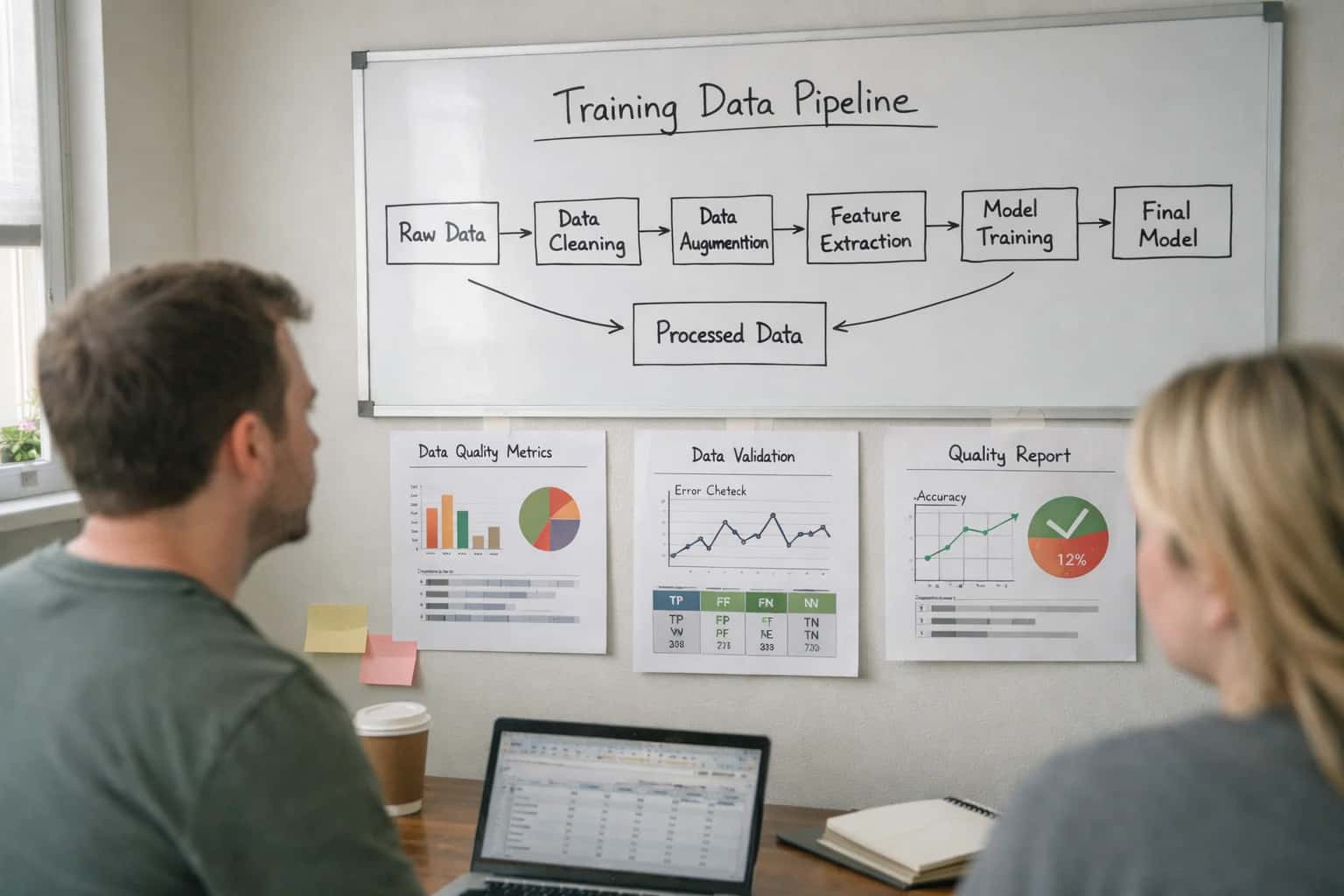
Monitoring Architecture Overview
Real-time energy monitoring is the observability layer for sustainable AI. It provides the data required to measure efficiency, optimize cooling, and reduce carbon footprint.
HARDWARE COMPARISON
Step 1: Select and Deploy Monitoring Hardware
Comparison of hardware options for instrumenting AI racks and GPU servers to capture granular energy and thermal data.
| Metric / Feature | Intelligent PDUs | DCIM Sensors | IoT Power Meters |
|---|---|---|---|
Primary Measurement | Per-outlet power (W) | Inlet/Outlet air temp (°C) | Circuit-level power (kW) |
Data Granularity | Per server/device | Per rack zone | Per power feed or PDU |
Installation Complexity | Medium (replace existing PDU) | Low (mount in rack) | High (requires electrical work) |
Integration with DCIM | |||
Cost per Measurement Point | $500 - $2k | $50 - $200 | $1k - $5k |
Accuracy | ±1% | ±0.5°C | ±0.5% |
Best For | Server-level power attribution | Thermal mapping and hot spot detection | Total cluster/rack energy intake |
Supports Liquid Cooling Monitoring |
IMPLEMENTATION
Step 2: Configure Data Collection Agents
Deploy software agents to collect granular power and thermal metrics from your AI hardware, establishing the data foundation for real-time monitoring.
Data collection agents are lightweight software processes that run on each server or at the rack level, polling sensors via vendor APIs and standard protocols. You will configure agents to scrape metrics from Intelligent PDUs for total rack power, NVIDIA DCGM for per-GPU utilization and temperature, and IoT sensors within liquid cooling loops for flow rate and coolant temperature. These agents transform raw telemetry into a structured time-series format, ready for streaming to your observability backend.
For a practical setup, use the open-source Telegraf agent with plugins for SNMP (PDUs), NVIDIA NVML (GPUs), and Modbus (cooling sensors). Configure each agent's telegraf.conf to tag data with location (e.g., rack=A1) and stream it to a time-series database like InfluxDB or Prometheus. This creates a unified data lake of energy and thermal performance, which is essential for the dashboards and alerts covered in our guide on How to Build a Carbon-Aware AI Compute Orchestrator.
Enabling Efficiency, Speed & Accuracy
Intelligent Analysis, Decision & Execution
We build AI systems for teams that need search across company data, workflow automation across tools, or AI features inside products and internal software.
Talk to Us
Search across company data
Give teams answers from docs, tickets, runbooks, and product data with sources and permissions.
Useful when people spend too long searching or get different answers from different systems.
Enterprise searchRAGPermissions
Read more
Automate internal workflows
Use AI to route work, draft outputs, trigger actions, and keep approvals and logs in place.
Useful when repetitive work moves across multiple tools and teams.
AI agentsWorkflow automationGovernance
Read more
Add AI to products and internal tools
Build assistants, guided actions, or decision support into the software your team or customers already use.
Useful when AI needs to be part of the product, not a separate tool.
AI integrationDecision supportModel routing
Read moreTROUBLESHOOTING
Common Mistakes
Setting up real-time energy monitoring for AI clusters is foundational for sustainable AI. These are the most frequent technical pitfalls that undermine data accuracy, system reliability, and actionable insights.
This is typically caused by incorrect sensor configuration or a mismatch between the measurement range and the actual load. Smart PDUs and IoT current transformers (CTs) must be configured for the correct voltage (e.g., 208V vs. 480V), phase (single or three-phase), and current scaling.
Common fixes:
- Verify the CT ratio setting in your sensor's software (e.g., a 200:5 CT must be configured as a 40:1 ratio).
- Ensure sensors are placed on the correct conductor and are fully clamped.
- Check for sensor saturation; a 100A CT on a circuit pulling 150A will give invalid data.
- Validate data in a tool like Grafana with a simple query before building complex dashboards.

About the author
Prasad Kumkar
CEO & MD, Inference Systems
Prasad Kumkar is the CEO & MD of Inference Systems and writes about AI systems architecture, LLM infrastructure, model serving, evaluation, and production deployment. Over 5+ years, he has worked across computer vision models, L5 autonomous vehicle systems, and LLM research, with a focus on taking complex AI ideas into real-world engineering systems.
His work and writing cover AI systems, large language models, AI agents, multimodal systems, autonomous systems, inference optimization, RAG, evaluation, and production AI engineering.
LinkedIn
Limited slotsGet a Free AI Consultation
Partnered with leading AI, data, and software stack.


How We Work
Custom AI workflows for your Business
One-fit-all AI don't work for modern businesses. At Inferensys, we aim to understand your business & custom requirements; which we use to define most efficient agentic workflows, the data, and the tools for your business.
01
Review the use case
We understand the task, the users, and where AI can actually help.
Read more02
Pick the right approach
We define what needs search, automation, or product integration.
Read more03
Build the first useful version
We implement the part that proves the value first.
Read more04
Improve from there
We add the checks and visibility needed to keep it useful.
Read moreThe first call is a practical review of your use case and the right next step.
Talk to Us