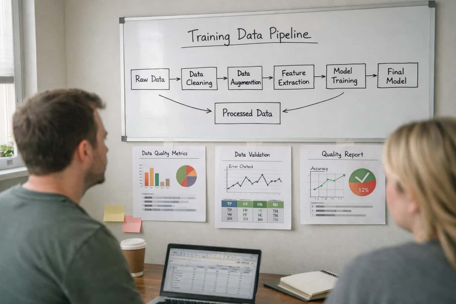
A real-time sensor fusion pipeline is the computational core that transforms raw, asynchronous data from disparate sensors into a single, coherent environmental model. This model must be temporally and spatially aligned, with conflicting or missing data resolved, to support safety-critical decisions like emergency braking or evasive steering. The design challenge is achieving deterministic latency—often under 100 milliseconds—while processing high-bandwidth streams within the constraints of a vehicle's zonal E/E architecture. This requires careful selection of fusion algorithms, from classical Kalman filters to deep sensor fusion networks, each with different computational profiles.
Guide
How to Design a Real-Time Sensor Fusion Pipeline for Vehicle Safety
A step-by-step guide to building a low-latency pipeline that fuses camera, radar, LiDAR, and ultrasonic data for safety-critical automotive applications.
This guide explains how to build a low-latency pipeline that fuses data from cameras, radar, LiDAR, and ultrasonic sensors for safety-critical applications.
Your implementation must be validated against ISO 26262 functional safety requirements, mandating robust handling of sensor dropout, data corruption, and common cause failures. Start by defining the pipeline's stages: raw data ingestion, timestamp synchronization, coordinate transformation, object association, and state estimation. Use a middleware like ROS 2 or AUTOSAR Adaptive for deterministic communication between these stages. Finally, integrate continuous validation using synthetic data and real-world edge cases to test the pipeline's resilience, a process foundational to broader MLOps and Model Lifecycle Management for Agents.
FOUNDATIONAL KNOWLEDGE
Key Concepts
Master the core principles for building a low-latency, safety-critical sensor fusion pipeline. These concepts form the bedrock of reliable perception for autonomous driving.
01
Temporal and Spatial Alignment
Before fusion, data from different sensors must be synchronized in time and transformed into a common coordinate frame. This is the most critical preprocessing step.
- Temporal Alignment: Compensate for differing sensor latencies and sampling rates using hardware timestamps and interpolation.
- Spatial Alignment: Use intrinsic and extrinsic calibration to project LiDAR points, radar returns, and camera pixels into a unified vehicle coordinate system (e.g., rear axle). Failure here introduces systematic errors that fusion cannot correct.
02
Fusion Algorithm Selection
Choose algorithms based on the required abstraction level and safety case.
- Low-Level (Data) Fusion: Combine raw sensor data (e.g., point clouds). Requires perfectly aligned data; computationally intensive.
- Mid-Level (Feature) Fusion: Fuse extracted features like bounding boxes or tracklets. Common for camera-radar fusion using Kalman Filters or Joint Probabilistic Data Association (JPDA).
- High-Level (Decision) Fusion: Run independent perception stacks and fuse their outputs (e.g., object lists). Provides redundancy but may miss weak signals.
- Deep Sensor Fusion Networks: End-to-end models (e.g., BEVFusion) learn to fuse features directly; powerful but less interpretable.
03
Functional Safety (ISO 26262) Integration
Designing for ASIL-B to ASIL-D is non-negotiable for safety-critical pipelines. This influences every architectural decision.
- Fail-Operational Design: Implement hardware and software redundancy so a single point of failure does not cause a hazardous event.
- Diagnostic Coverage: Use diverse sensor validation and plausibility checks to detect sensor failures or signal degradation in real-time.
- Safety of the Intended Functionality (SOTIF): Address performance limitations and edge cases (e.g., sensor blinding) that aren't traditional faults. This requires extensive scenario-based testing.
04
Handling Sensor Dropout & Conflict
Real-world conditions cause sensors to fail or disagree. The pipeline must be robust.
- Sensor Dropout: Implement confidence-based weighting or fallback to a reduced sensor set. Use predictive models to fill short gaps.
- Conflicting Data: Establish a voting or arbitration logic. For example, prioritize LiDAR for precise distance but camera for semantic classification. Track sensor health to de-weight unreliable sources.
- Dynamic Reconfiguration: The system should adapt its fusion strategy based on environmental conditions (e.g., heavy rain degrading camera performance).
05
Latency Budget & Real-Time Constraints
A safety system has a hard deadline from sensor measurement to actuator command.
- Define the Total Allowable Latency (e.g., < 100ms for automatic emergency braking).
- Budget the Pipeline: Allocate time for sensor readout, communication, alignment, fusion, and decision-making.
- Optimize for Worst-Case Execution Time (WCET), not average. This often dictates the choice of algorithms (e.g., a Kalman filter over a particle filter) and hardware (dedicated vs. shared compute).
06
Validation & Ground Truth
Proving the pipeline works requires rigorous testing against high-fidelity truth data.
- Use Multi-Sensor Ground Truth Rigs that combine high-end survey-grade sensors (e.g., RTK-GPS, high-res LiDAR) to generate reference data.
- Create a Scenario Database covering edge cases: occlusions, adverse weather, and sensor failure modes.
- Metrics: Track object-level metrics (precision, recall) and critical safety metrics like time-to-collision (TTC) error. This process is foundational for achieving SOTIF and certification.
FOUNDATION
Define Safety and Performance Requirements
The first and most critical step in designing a real-time sensor fusion pipeline is establishing non-negotiable safety and performance targets. These requirements dictate every subsequent architectural and algorithmic choice.
Begin by defining functional safety requirements according to ISO 26262. This involves classifying your fusion pipeline's Automotive Safety Integrity Level (ASIL), which determines the necessary fault tolerance, diagnostic coverage, and development processes. For a safety-critical application like emergency braking, you likely target ASIL-D, the highest level. Concurrently, establish performance requirements: maximum allowable latency (e.g., <100ms end-to-end), data freshness, and accuracy thresholds for object detection and tracking. These metrics are your system's contract.
Translate these targets into technical specifications. For latency, calculate the budget for each stage: sensor readout, network transmission to the zonal controller, temporal alignment, fusion algorithm execution, and output to the actuator. For safety, specify redundancy strategies (e.g., dual compute paths) and fail-operational behaviors. Document these as verifiable requirements; they will guide your selection of sensor fusion algorithms like Kalman filters or deep networks and inform the design of your validation suite against ISO 26262 mandates.
CORE ALGORITHMS
Sensor Fusion Algorithm Comparison
A comparison of primary sensor fusion algorithms for combining camera, radar, and LiDAR data in a real-time vehicle safety pipeline. Selection depends on latency, computational cost, and functional safety requirements.
| Algorithm / Feature | Kalman Filter (Extended) | Deep Sensor Fusion Network | Bayesian Occupancy Filter |
|---|---|---|---|
Fusion Level | Low-level (Raw/Feature) | Mid-to-High-level (Feature/Object) | Low-level (Grid-based) |
Latency (Typical) | < 1 ms | 10-50 ms | 5-20 ms |
Handles Non-Linear Dynamics | |||
Handles Sensor Dropout | |||
Explicit Uncertainty Modeling | |||
ISO 26262 ASIL-D Certification Path | Well-established | Emerging / Complex | Established |
Computational Load (Relative) | Low | Very High | Medium |
Explainability / Debugging | High | Low (Black-box) | Medium |
FUNCTIONAL SAFETY
Step 5: Validate Against ISO 26262
This final step ensures your sensor fusion pipeline meets the rigorous functional safety standards required for automotive deployment, transforming a prototype into a safety-certifiable system.
ISO 26262 validation is a systematic process, not a single test. You must demonstrate that your pipeline's Safety Goals are met through a combination of verification (testing the implementation) and validation (proving it works in the real world). This involves executing your Safety Plan, which includes fault injection tests to verify error handling, quantitative analysis of Diagnostic Coverage, and formal verification of critical algorithms like your Kalman filter or fusion logic. The output is a Safety Case—a structured argument supported by evidence that the system is acceptably safe for its intended use.
Key deliverables include the Safety Case document, a Software Verification Report, and Hardware-Software Interface (HSI) specifications. Common mistakes are treating this as a final checkbox activity instead of integrating safety from the start, and failing to maintain a complete, traceable tool chain qualification record for all compilers and libraries used. For managing the lifecycle of these safety-critical models, review our guide on MLOps and Model Lifecycle Management for Agents. To ensure your system's reasoning is auditable, align with principles for Explainability and Traceability for High-Risk AI.
Enabling Efficiency, Speed & Accuracy
Intelligent Analysis, Decision & Execution
We build AI systems for teams that need search across company data, workflow automation across tools, or AI features inside products and internal software.
Talk to Us
Search across company data
Give teams answers from docs, tickets, runbooks, and product data with sources and permissions.
Useful when people spend too long searching or get different answers from different systems.
Enterprise searchRAGPermissions
Read more
Automate internal workflows
Use AI to route work, draft outputs, trigger actions, and keep approvals and logs in place.
Useful when repetitive work moves across multiple tools and teams.
AI agentsWorkflow automationGovernance
Read more
Add AI to products and internal tools
Build assistants, guided actions, or decision support into the software your team or customers already use.
Useful when AI needs to be part of the product, not a separate tool.
AI integrationDecision supportModel routing
Read moreTROUBLESHOOTING
Common Mistakes
Building a real-time sensor fusion pipeline for vehicle safety is a high-stakes engineering challenge. These are the most frequent technical pitfalls developers encounter and how to fix them.
High latency often stems from improper temporal alignment and inefficient data flow. Sensors like cameras (30-60 Hz) and LiDAR (10-20 Hz) operate at different rates. A common mistake is processing data as it arrives, causing the pipeline to wait for the slowest sensor.
Fix: Implement a centralized time synchronization mechanism, like PTP (Precision Time Protocol), to timestamp all sensor data. Use a predictive buffer to hold and align data to a common clock cycle before fusion. Architect your pipeline to process the latest aligned frame rather than waiting for all raw inputs.

About the author
Prasad Kumkar
CEO & MD, Inference Systems
Prasad Kumkar is the CEO & MD of Inference Systems and writes about AI systems architecture, LLM infrastructure, model serving, evaluation, and production deployment. Over 5+ years, he has worked across computer vision models, L5 autonomous vehicle systems, and LLM research, with a focus on taking complex AI ideas into real-world engineering systems.
His work and writing cover AI systems, large language models, AI agents, multimodal systems, autonomous systems, inference optimization, RAG, evaluation, and production AI engineering.
LinkedIn
Limited slotsGet a Free AI Consultation
Partnered with leading AI, data, and software stack.


How We Work
Custom AI workflows for your Business
One-fit-all AI don't work for modern businesses. At Inferensys, we aim to understand your business & custom requirements; which we use to define most efficient agentic workflows, the data, and the tools for your business.
01
Review the use case
We understand the task, the users, and where AI can actually help.
Read more02
Pick the right approach
We define what needs search, automation, or product integration.
Read more03
Build the first useful version
We implement the part that proves the value first.
Read more04
Improve from there
We add the checks and visibility needed to keep it useful.
Read moreThe first call is a practical review of your use case and the right next step.
Talk to Us