Supervisory Control and Data Acquisition (SCADA) is a centralized control system architecture that collects real-time telemetry from remote terminal units (RTUs) and Intelligent Electronic Devices (IEDs) in substations, presenting a unified human-machine interface (HMI) to operators for monitoring, alarm management, and supervisory control of the high-voltage grid.

Glossary
Supervisory Control and Data Acquisition (SCADA)
A centralized control system architecture that collects real-time data from remote substation RTUs and IEDs, presenting it to human operators for monitoring, alarm management, and supervisory control of the power grid.
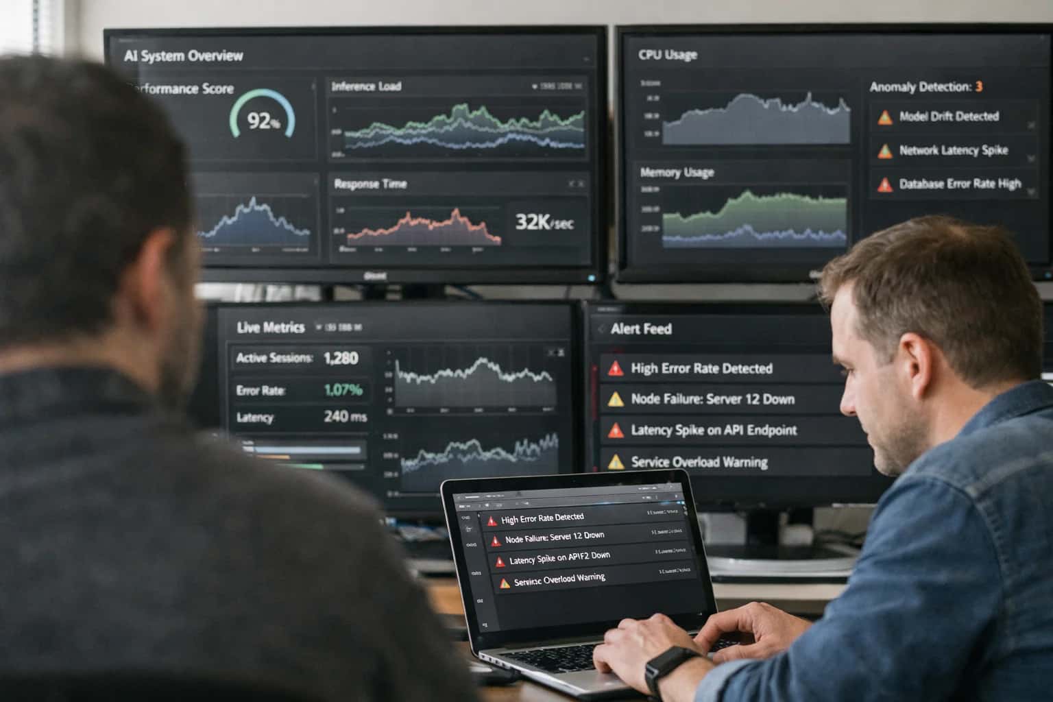
CENTRALIZED GRID CONTROL ARCHITECTURE
What is Supervisory Control and Data Acquisition (SCADA)?
SCADA is the centralized nervous system of the power grid, providing real-time visibility and supervisory control over geographically dispersed substation assets.
SCADA systems execute supervisory control commands—such as opening a circuit breaker or adjusting a tap changer—using protocols like DNP3 and IEC 60870-5-101/104, while relying on local automation for high-speed protection. Modern architectures integrate with IEC 61850 gateways to bridge legacy SCADA polling with event-driven GOOSE messaging.
SYSTEM ANATOMY
Core Components of a SCADA Architecture
A Supervisory Control and Data Acquisition (SCADA) system is a centralized architecture that collects real-time telemetry from geographically dispersed field devices, presents it to human operators for situational awareness, and executes supervisory control commands. The following components form the canonical functional layers of a modern power utility SCADA deployment.
01
Human-Machine Interface (HMI)
The Human-Machine Interface is the graphical presentation layer that translates raw grid telemetry into actionable visual schematics for operators. It renders single-line diagrams, animated breaker status indicators, and real-time trend charts. Modern HMIs incorporate alarm annunciation systems with priority filtering to prevent operator cognitive overload during cascading events. The interface must support sub-second refresh rates for critical analog values like bus voltages and frequency while logging all operator interactions for NERC CIP compliance auditing.
02
Master Terminal Unit (MTU)
The Master Terminal Unit acts as the central processing server cluster that polls remote stations, aggregates data, and maintains the system's real-time database. It executes the scan cycle—a deterministic loop that sequentially requests updated values from RTUs and IEDs using protocols like DNP3 or IEC 60870-5-101/104. The MTU is typically deployed in a hot-standby redundant configuration to ensure continuous operations during hardware failure, with automatic database synchronization between primary and backup servers.
03
Remote Terminal Unit (RTU)
A Remote Terminal Unit is a ruggedized field computer installed at substations that serves as the data concentration point between physical equipment and the control center. It interfaces directly with transducers, potential transformers, and current transformers to digitize analog measurements. Key functions include:
- Time-stamping events with millisecond accuracy
- Executing local automation logic during communication loss
- Supporting report-by-exception to minimize bandwidth
- Converting legacy serial device protocols to IP-based SCADA protocols
04
Communication Infrastructure
The communication network forms the nervous system connecting the MTU to geographically dispersed RTUs and IEDs. Utility SCADA systems employ a layered topology: fiber-optic SONET rings for backbone transmission, licensed microwave for remote substations, and narrowband radio for distribution automation. Modern architectures are migrating to MPLS-TP packet-switched networks with traffic engineering to guarantee deterministic latency for critical teleprotection signals. Serial tunneling over IP preserves legacy protocol investments during this transition.
05
Programmable Logic Controller (PLC)
Within the SCADA hierarchy, Programmable Logic Controllers execute high-speed, deterministic control loops at the field level that are too time-sensitive for the MTU scan cycle. They perform closed-loop PID control for voltage regulation and capacitor bank switching based on local measurements. PLCs communicate with the supervisory layer via register mapping, where specific memory addresses are exposed to the RTU or MTU for read/write operations. Ladder logic programming remains prevalent for its reliability and ease of troubleshooting by field technicians.
06
Data Historian
The Data Historian is a time-series database optimized for ingesting high-velocity SCADA telemetry streams and storing them for long-term analysis. Unlike the MTU's real-time database, which holds only current values, the historian archives every state change and analog sample with compression algorithms like swinging door to reduce storage footprint without losing significant trends. This repository enables forensic analysis of grid disturbances, regulatory reporting, and training datasets for predictive maintenance machine learning models.
CONTROL HIERARCHY COMPARISON
SCADA vs. Substation Automation System (SAS)
Distinguishing the centralized, wide-area supervisory role of SCADA from the localized, high-speed protection and control functions of a Substation Automation System.
| Feature | SCADA | Substation Automation System (SAS) |
|---|---|---|
Primary Function | Centralized supervisory control, data acquisition, and alarm management across multiple substations | Localized protection, interlocking, and automated control within a single substation |
Operational Scope | Wide-area (entire grid region or utility territory) | Station-wide (single substation bay or voltage level) |
Typical Latency | 2-10 seconds (non-critical polling) | < 3 milliseconds (GOOSE tripping) |
Key Protocols | IEC 60870-5-101/104, DNP3, Modbus | IEC 61850 (GOOSE, Sampled Values, MMS) |
Time Synchronization Requirement | Millisecond accuracy (NTP/SNTP) | Sub-microsecond accuracy (PTP IEEE 1588) |
Human-Machine Interface | ||
High-Speed Protection Interlocking | ||
Historical Data Archiving |
SCADA FUNDAMENTALS
Frequently Asked Questions
Clear, technically precise answers to the most common questions about Supervisory Control and Data Acquisition systems in modern power grid operations.
Supervisory Control and Data Acquisition (SCADA) is a centralized control system architecture that collects real-time telemetry from geographically dispersed field devices—such as Remote Terminal Units (RTUs) and Intelligent Electronic Devices (IEDs)—and presents this data to human operators for monitoring, alarm management, and supervisory control. In a power grid, SCADA operates as a closed-loop system: Remote Terminal Units at substations continuously scan analog inputs (voltage, current, MW, MVAR) and digital status points (breaker position, tap changer position), time-stamp the data, and transmit it to a Master Terminal Unit (MTU) via protocols like DNP3 or IEC 60870-5-101/104. The MTU processes this data, updates the Human-Machine Interface (HMI), checks for limit violations, and logs events to a historian. Operators can then issue supervisory commands—such as opening a circuit breaker or raising a transformer tap—which are transmitted back to the RTU for execution. Critically, SCADA provides wide-area visibility but typically operates on scan rates of 2-10 seconds, making it suitable for steady-state monitoring rather than high-speed protection functions, which are handled locally by IEDs using GOOSE messaging.
Enabling Efficiency, Speed & Accuracy
Intelligent Analysis, Decision & Execution
We build AI systems for teams that need search across company data, workflow automation across tools, or AI features inside products and internal software.
Talk to Us
Search across company data
Give teams answers from docs, tickets, runbooks, and product data with sources and permissions.
Useful when people spend too long searching or get different answers from different systems.
Enterprise searchRAGPermissions
Read more
Automate internal workflows
Use AI to route work, draft outputs, trigger actions, and keep approvals and logs in place.
Useful when repetitive work moves across multiple tools and teams.
AI agentsWorkflow automationGovernance
Read more
Add AI to products and internal tools
Build assistants, guided actions, or decision support into the software your team or customers already use.
Useful when AI needs to be part of the product, not a separate tool.
AI integrationDecision supportModel routing
Read more
About the author
Prasad Kumkar
CEO & MD, Inference Systems
Prasad Kumkar is the CEO & MD of Inference Systems and writes about AI systems architecture, LLM infrastructure, model serving, evaluation, and production deployment. Over 5+ years, he has worked across computer vision models, L5 autonomous vehicle systems, and LLM research, with a focus on taking complex AI ideas into real-world engineering systems.
His work and writing cover AI systems, large language models, AI agents, multimodal systems, autonomous systems, inference optimization, RAG, evaluation, and production AI engineering.
LinkedIn
Limited slotsGet a Free AI Consultation
Partnered with leading AI, data, and software stack.





How We Work
Custom AI workflows for your Business
One-fit-all AI don't work for modern businesses. At Inferensys, we aim to understand your business & custom requirements; which we use to define most efficient agentic workflows, the data, and the tools for your business.
01
Review the use case
We understand the task, the users, and where AI can actually help.
Read more02
Pick the right approach
We define what needs search, automation, or product integration.
Read more03
Build the first useful version
We implement the part that proves the value first.
Read more04
Improve from there
We add the checks and visibility needed to keep it useful.
Read moreThe first call is a practical review of your use case and the right next step.
Talk to Us