Interlocking is a safety-critical logic function within a Substation Automation System (SAS) that prevents the execution of a switching command—such as opening a disconnector under load—unless a predefined set of permissive conditions, derived from the real-time status of circuit breakers, disconnectors, and earth switches, evaluates as true. It enforces the physical rules of safe switchgear operation.

Glossary
Interlocking
A safety logic function implemented in substation automation systems that prevents dangerous switching operations by evaluating the real-time status of connected equipment, such as disconnectors and circuit breakers.
SUBSTATION SAFETY LOGIC
What is Interlocking?
A hardwired or software-based safety function that prevents dangerous switching operations by evaluating the real-time status of connected switchgear.
In modern IEC 61850 digital substations, interlocking logic is implemented using GOOSE messages exchanged between Intelligent Electronic Devices (IEDs) over the station bus, replacing traditional hardwired auxiliary contacts. The logic evaluates the topology of the bay, ensuring that a disconnector cannot be operated while its associated circuit breaker is closed, thereby preventing catastrophic arc flash incidents and equipment destruction.
SAFETY LOGIC
Key Characteristics of Interlocking
Interlocking is a hardwired or software-based safety logic function that prevents dangerous switching operations by evaluating the real-time status of connected equipment. It ensures that disconnectors cannot be operated under load and that earthing switches cannot be closed on live circuits.
01
Bay-Level Topology Evaluation
Interlocking logic continuously evaluates the real-time topology of a substation bay. It reads the open/close status of all relevant circuit breakers, disconnectors, and earthing switches via GOOSE messages or hardwired binary inputs. The logic prevents a disconnector from opening or closing if the associated circuit breaker is still closed, enforcing the fundamental rule that disconnectors must not interrupt load current. This evaluation is typically implemented in the bay controller IED and operates with deterministic speed.
02
Station-Wide Interlocking
Beyond individual bays, interlocking extends across the entire substation to manage complex configurations like busbar transfers and bus coupler operations. For example, when transferring a feeder from one busbar to another, the logic ensures the bus coupler and associated disconnectors are in a safe sequence before any operation is permitted. This station-wide view prevents operators from accidentally isolating a bus section or creating an unsafe parallel connection between different voltage sources.
03
GOOSE-Based Implementation
In modern IEC 61850 substations, interlocking signals are exchanged between IEDs using GOOSE (Generic Object Oriented Substation Event) messages over the station bus. This replaces hundreds of copper wires with a single fiber-optic network. Key characteristics include:
- Publisher-subscriber model: A circuit breaker IED publishes its status; all bay controllers subscribe to it
- Sub-millisecond latency: Critical for operational safety
- Continuous supervision: GOOSE messages include a heartbeat, so any communication failure is detected immediately and triggers a fail-safe state
04
Select-Before-Operate Integration
Interlocking is tightly integrated with the Select-Before-Operate (SBO) control sequence. When an operator selects a switching device via the HMI or SCADA, the interlocking logic evaluates the current topology and returns either a release or block signal. Only if the interlocking conditions are satisfied does the SBO sequence proceed to the operate step. This two-step process provides a critical defense against both human error and software glitches.
05
Fail-Safe Design Philosophy
Interlocking systems are designed with a fail-safe principle: any loss of communication, power supply failure, or IED malfunction must result in a blocked state, never a false release. This is achieved through:
- Default block on timeout: If a GOOSE message from a critical circuit breaker is not received within its time-to-live, the interlocking logic assumes the worst case
- Redundant communication paths: Using PRP or HSR protocols to eliminate single points of failure
- Hardwired backup: For the most critical interlocks, a direct copper connection may supplement the digital logic
06
Testing and Simulation
Interlocking logic must be rigorously tested before commissioning. Engineers use Substation Configuration Language (SCL) files to define the expected behavior and then validate it through Hardware-in-the-Loop (HIL) simulation. The HIL simulator injects GOOSE messages representing various breaker and disconnector states, and the test system verifies that the bay controller's interlocking outputs match the expected results for every possible topological combination, including fault scenarios.
Enabling Efficiency, Speed & Accuracy
Intelligent Analysis, Decision & Execution
We build AI systems for teams that need search across company data, workflow automation across tools, or AI features inside products and internal software.
Talk to Us
Search across company data
Give teams answers from docs, tickets, runbooks, and product data with sources and permissions.
Useful when people spend too long searching or get different answers from different systems.
Enterprise searchRAGPermissions
Read more
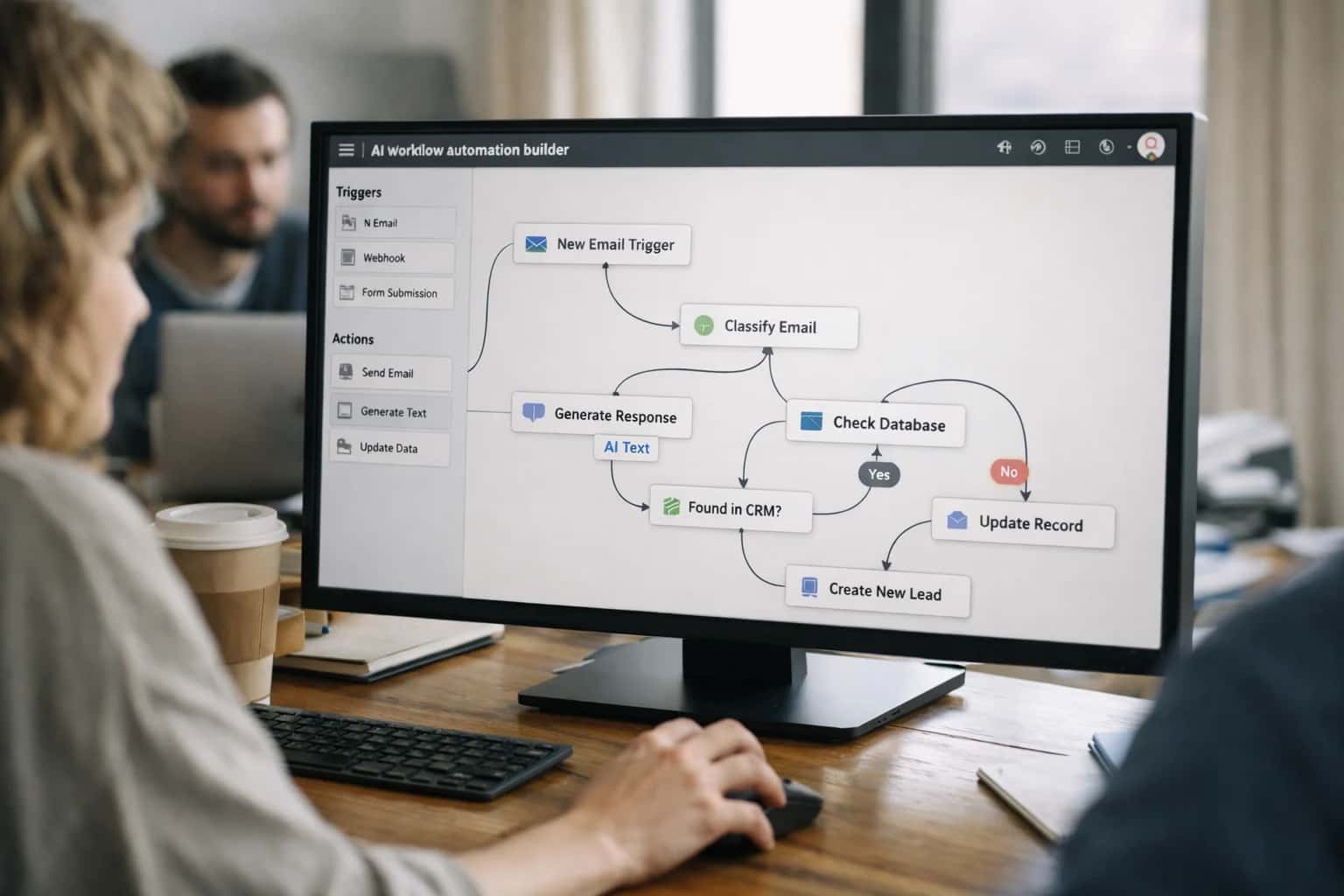
Automate internal workflows
Use AI to route work, draft outputs, trigger actions, and keep approvals and logs in place.
Useful when repetitive work moves across multiple tools and teams.
AI agentsWorkflow automationGovernance
Read more
Add AI to products and internal tools
Build assistants, guided actions, or decision support into the software your team or customers already use.
Useful when AI needs to be part of the product, not a separate tool.
AI integrationDecision supportModel routing
Read moreINTERLOCKING LOGIC
Frequently Asked Questions
Clear, technical answers to the most common questions about substation interlocking schemes, their implementation in IEC 61850 systems, and their role in preventing catastrophic switching errors.
Interlocking is a safety-critical logic function implemented in substation automation systems that prevents dangerous switching operations by evaluating the real-time status of connected equipment, such as disconnectors and circuit breakers. The primary objective is to enforce operational rules that ensure a disconnector can only be operated when its associated circuit breaker is open and under no-load conditions, thereby preventing the switching of energized circuits which would cause severe arcing and equipment destruction. This logic is typically executed within bay-level Intelligent Electronic Devices (IEDs) using IEC 61850 data models, evaluating the open/closed status of relevant switchgear before releasing or blocking a control command. Interlocking represents a hard-wired or software-based defense against human error, ensuring that the physical laws of safe switching are never violated regardless of operator intent.

About the author
Prasad Kumkar
CEO & MD, Inference Systems
Prasad Kumkar is the CEO & MD of Inference Systems and writes about AI systems architecture, LLM infrastructure, model serving, evaluation, and production deployment. Over 5+ years, he has worked across computer vision models, L5 autonomous vehicle systems, and LLM research, with a focus on taking complex AI ideas into real-world engineering systems.
His work and writing cover AI systems, large language models, AI agents, multimodal systems, autonomous systems, inference optimization, RAG, evaluation, and production AI engineering.
LinkedIn
Limited slotsGet a Free AI Consultation
Partnered with leading AI, data, and software stack.





How We Work
Custom AI workflows for your Business
One-fit-all AI don't work for modern businesses. At Inferensys, we aim to understand your business & custom requirements; which we use to define most efficient agentic workflows, the data, and the tools for your business.
01
Review the use case
We understand the task, the users, and where AI can actually help.
Read more02
Pick the right approach
We define what needs search, automation, or product integration.
Read more03
Build the first useful version
We implement the part that proves the value first.
Read more04
Improve from there
We add the checks and visibility needed to keep it useful.
Read moreThe first call is a practical review of your use case and the right next step.
Talk to Us