Hardware-in-the-Loop (HIL) testing is a validation methodology where physical robot hardware—such as actuators, sensors, or embedded controllers—is connected in real-time to a high-fidelity software simulation that provides virtual environmental feedback. This creates a closed-loop system where the physical components interact with a simulated world, enabling rigorous, safe, and repeatable testing of control policies, perception algorithms, and overall system integration before deployment in the real world. It is a cornerstone technique for sim-to-real transfer and policy deployment.

Glossary
Hardware-in-the-Loop (HIL)
Hardware-in-the-Loop (HIL) is a validation methodology where physical robot hardware is connected in real-time to a simulation that provides virtual environmental feedback.
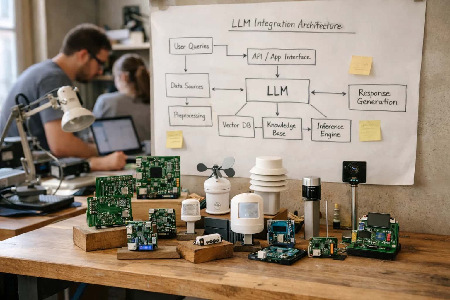
VALIDATION METHODOLOGY
What is Hardware-in-the-Loop (HIL)?
Hardware-in-the-Loop (HIL) testing is a critical validation methodology in robotics and autonomous systems development, bridging the gap between pure simulation and full physical deployment.
The core value of HIL testing lies in its ability to expose dynamics mismatch and observation space mismatch in a controlled setting. By injecting realistic sensor noise, communication latency, and actuator dynamics into the loop, engineers can evaluate policy robustness and identify safety constraints violations. This process is essential for digital twin validation and is often a precursor to shadow mode deployment, providing a critical risk mitigation layer in the development of embodied intelligence systems and autonomous supply chain intelligence.
HARDWARE-IN-THE-LOOP
Core Components of a HIL System
A Hardware-in-the-Loop (HIL) system is a closed-loop test architecture that integrates physical robot components with a real-time simulation of the environment. Its core components enable safe, repeatable, and high-fidelity validation of control policies before full physical deployment.
01
Real-Time Simulation Engine
The real-time simulation engine is the computational core that models the virtual environment and its physics with deterministic timing guarantees. It must execute simulation steps at a fixed, high frequency (often 1 kHz or faster) to accurately interact with physical hardware.
- Key Function: Solves rigid body dynamics, contact forces, and sensor models within a strict timing budget.
- Examples: NVIDIA Isaac Sim, Unity with ROS-TCP-Connector, proprietary engines built on Bullet or MuJoCo.
- Critical Requirement: Hard real-time execution is non-negotiable; missed deadlines cause system instability and invalidate test results.
02
Physical Hardware Interface
The physical hardware interface comprises the I/O hardware and low-level drivers that connect the simulation to the actual robot components. This layer handles the bidirectional conversion between digital signals and physical actuation/sensing.
- Components: Real-time I/O cards (e.g., from National Instruments or Speedgoat), motor drivers, sensor signal conditioners, and safety relays.
- Function: It transmits simulated sensor data (e.g., encoder pulses, camera feeds) to the robot's controller and reads back actuator commands from the embedded control unit.
- Latency: Total loop latency (simulation + I/O) must be minimized and characterized to ensure test fidelity.
03
Embedded Control Unit (ECU)
The Embedded Control Unit (ECU) is the actual robot's onboard computer or microcontroller that runs the control policy under test. In HIL, it is fed simulated sensor data and its output commands are sent to the simulated actuators.
- Purpose: Validates the policy deployment on the exact target hardware, including its real-time operating system (RTOS), compilers, and computational limits.
- Testing Scope: This tests not just the algorithm, but also sensor fusion pipelines, state estimation code, and communication buses (CAN, Ethernet) in a realistic workload.
- Benefit: Catches integration bugs, timing issues, and memory constraints that are invisible in pure software-in-the-loop (SIL) testing.
04
Virtual Sensor Models
Virtual sensor models are high-fidelity software emulations of the robot's physical sensors, generating the synthetic data stream fed to the ECU. Their accuracy directly impacts the validity of the HIL test.
- Types: Models for cameras (with realistic noise, distortion, and latency), LiDAR (raycasting with material properties), IMUs, force-torque sensors, and joint encoders.
- Challenge: Must replicate non-ideal characteristics like sensor noise, dropouts, calibration errors, and communication delays to stress-test the policy's robustness.
- Output: These models feed the observation space of the policy, creating a controlled covariate shift from training simulation to HIL test.
05
Actuator & Dynamics Plant Model
The actuator and dynamics plant model is the simulated counterpart to the robot's physical body. It receives torque or position commands from the ECU and calculates the resulting motion, which is then sensed by the virtual sensors.
- Components: Includes motor dynamics (saturation, backlash, thermal limits), transmission models (gearbox efficiency), and full multi-body kinematics and dynamics.
- Calibration: Often refined via system identification using data from the real hardware to minimize dynamics mismatch.
- Role: Closes the control loop within the simulation. A high-fidelity plant model is essential for testing Model Predictive Control (MPC) or other model-based controllers.
06
Test Orchestration & Monitoring Suite
The test orchestration and monitoring suite is the supervisory software that automates test execution, injects faults, logs all data, and provides observability into the HIL loop.
- Capabilities:
- Scenario Automation: Sequences through predefined test cases (e.g.,
pick-and-place,stair climbing). - Fault Injection: Simulates sensor failures, network latency spikes, or actuator jams to test safety constraints.
- Data Logging: Records every signal (simulated and physical) with microsecond timestamps for post-test benchmarking and debugging.
- Real-Time Visualization: Provides live plots of states, rewards, and uncertainty quantification metrics.
- Scenario Automation: Sequences through predefined test cases (e.g.,
- Output: Generates pass/fail reports and quantitative metrics on policy robustness and performance regression.
VALIDATION METHODOLOGY
How Hardware-in-the-Loop Testing Works
A technical overview of the Hardware-in-the-Loop (HIL) testing process, a critical validation step in sim-to-real transfer for robotics.
Hardware-in-the-Loop (HIL) testing is a validation methodology where physical robot hardware—such as actuators, sensors, or embedded controllers—is connected in real-time to a high-fidelity simulation that provides virtual environmental feedback. This closed-loop system allows engineers to execute and test control policies against simulated physics and sensor models before full physical deployment, enabling safe, repeatable, and accelerated validation of software on actual silicon and mechanical components.
The core mechanism involves a real-time simulation engine that models the robot's environment and dynamics, sending simulated sensor signals (e.g., camera images, joint positions) to the physical hardware's input ports. The hardware's controller processes these signals and computes actuation commands, which are fed back into the simulation to update the virtual state. This loop rigorously tests for latency, sensor noise handling, and dynamics mismatch in a controlled setting, directly informing system identification and policy robustness prior to risky real-world trials.
HARDWARE-IN-THE-LOOP (HIL)
Primary Use Cases and Applications
Hardware-in-the-Loop (HIL) testing is a critical validation methodology that connects physical robot hardware to a real-time simulation, enabling safe, repeatable, and comprehensive testing of control policies before full physical deployment.
01
Control Policy Validation
HIL testing provides the definitive environment for validating simulation-trained control policies before they command a physical robot. The physical actuators and sensors are connected to a simulated environment, allowing engineers to:
- Test the policy's closed-loop performance with real hardware latency and noise.
- Verify that reward functions and safety constraints translate correctly from simulation.
- Identify and debug issues related to dynamics mismatch or observation space mismatch in a controlled setting.
02
Safety-Critical Failure Mode Testing
HIL enables exhaustive testing of edge cases and failure modes that would be dangerous, destructive, or impossible to replicate safely with a full physical system. This includes:
- Simulating sensor failures (e.g., camera occlusion, IMU drift) to validate fault-tolerant control.
- Injecting extreme environmental perturbations (e.g., strong gusts, slippery surfaces) to test policy robustness.
- Enforcing and testing safety constraints (e.g., joint torque limits, obstacle avoidance) against virtual obstacles and forces.
03
Hardware and Firmware Integration
This application focuses on verifying the integration between high-level AI policies and low-level hardware controllers. HIL testing is used to:
- Validate communication protocols and data pipelines between the policy inference engine and motor controllers.
- Benchmark end-to-end latency from sensor input to actuator command.
- Test and calibrate embedded firmware updates alongside new control policies, ensuring the entire stack functions cohesively under simulated load.
04
Sensor Simulation and Calibration
HIL systems often replace physical sensors with simulated sensor feeds, or use them in tandem, to test perception pipelines. Key uses include:
- Feeding synthetic camera images, LiDAR point clouds, or proprioceptive data from the simulation directly to the policy, bypassing physical sensors to isolate perception algorithms.
- Calibrating real sensors by comparing their outputs against ground-truth simulation data.
- Testing sensor fusion algorithms with perfectly aligned simulated and real sensor streams.
05
Digital Twin Validation and Refinement
HIL serves as a critical feedback loop for improving the accuracy of the digital twin or simulation model itself. By comparing the real hardware's response to simulated commands, engineers can:
- Perform system identification to refine simulation parameters (e.g., friction coefficients, motor constants).
- Quantify the reality gap or simulation bias for specific hardware units.
- Collect paired data (simulated action / real reaction) to train dynamics models for more accurate future simulation.
06
Regression Testing and CI/CD for Robotics
HIL setups enable automated, repeatable testing suites that can be integrated into a Continuous Integration/Continuous Deployment (CI/CD) pipeline for robotic software. This allows teams to:
- Run a battery of tests on every policy or firmware commit against the same physical hardware interface.
- Ensure new updates do not introduce regressions in performance or violate safety envelopes.
- Maintain a benchmarking baseline for system performance over time, using the consistent interface of the HIL rig.
VALIDATION METHODOLOGY COMPARISON
HIL vs. Other Validation Methods
A comparison of Hardware-in-the-Loop testing against other common validation strategies for robotics and autonomous systems, highlighting trade-offs in realism, cost, safety, and scalability.
| Validation Feature | Hardware-in-the-Loop (HIL) | Pure Simulation | Full Physical Prototyping |
|---|---|---|---|
Real Hardware Integration | |||
Real-Time Execution Constraints | |||
Environmental Realism | Virtual Environment | Virtual Environment | Physical Environment |
Test Repeatability & Control | High (Deterministic sim) | Perfect (Deterministic) | Low (Stochastic real world) |
Safety for Hardware | High (Failsafe in sim) | N/A (No hardware) | Low (Risk of damage) |
Cost per Test Iteration | $10-100 (Compute + wear) | < $1 (Compute only) | $100-10k+ (Material/repair) |
Ability to Test Edge/Failure Cases | High (Controlled injection) | Perfect (Full control) | Very Low (High risk) |
Test Setup & Configuration Time | Hours to days | Minutes | Days to weeks |
Scalability (Parallel Tests) | High (Many sim instances) | Very High (Massive parallelism) | Very Low (Physical bottleneck) |
Identifies Dynamics Mismatch | |||
Identifies Sensor/Actuator Latency | |||
Fidelity to Final Deployed System | High (Real compute & I/O) | Low (Abstracted stack) | Perfect (Actual system) |
HARDWARE-IN-THE-LOOP
Frequently Asked Questions
Hardware-in-the-Loop (HIL) testing is a critical validation methodology in robotics and autonomous systems. It connects physical hardware to a real-time simulation, enabling safe, repeatable, and comprehensive testing of control policies before full physical deployment.
Hardware-in-the-Loop (HIL) testing is a validation methodology where physical robot hardware—such as actuators, sensors, or embedded controllers—is connected in real-time to a simulation that provides virtual environmental feedback. It works by creating a closed-loop system: the physical hardware executes control commands, its outputs are measured, and these measurements are fed into a high-fidelity simulation running on a real-time operating system (RTOS). The simulation calculates the resulting state of the virtual environment and generates synthetic sensor data (e.g., camera images, lidar point clouds, joint torques), which is then sent back to the hardware as input. This allows the complete cyber-physical system to be tested under a vast range of simulated conditions without the risks, costs, and repeatability challenges of testing in the real world.
Enabling Efficiency, Speed & Accuracy
Intelligent Analysis, Decision & Execution
We build AI systems for teams that need search across company data, workflow automation across tools, or AI features inside products and internal software.
Talk to Us
Search across company data
Give teams answers from docs, tickets, runbooks, and product data with sources and permissions.
Useful when people spend too long searching or get different answers from different systems.
Enterprise searchRAGPermissions
Read more
Automate internal workflows
Use AI to route work, draft outputs, trigger actions, and keep approvals and logs in place.
Useful when repetitive work moves across multiple tools and teams.
AI agentsWorkflow automationGovernance
Read more
Add AI to products and internal tools
Build assistants, guided actions, or decision support into the software your team or customers already use.
Useful when AI needs to be part of the product, not a separate tool.
AI integrationDecision supportModel routing
Read more
About the author
Prasad Kumkar
CEO & MD, Inference Systems
Prasad Kumkar is the CEO & MD of Inference Systems and writes about AI systems architecture, LLM infrastructure, model serving, evaluation, and production deployment. Over 5+ years, he has worked across computer vision models, L5 autonomous vehicle systems, and LLM research, with a focus on taking complex AI ideas into real-world engineering systems.
His work and writing cover AI systems, large language models, AI agents, multimodal systems, autonomous systems, inference optimization, RAG, evaluation, and production AI engineering.
LinkedIn
Limited slotsGet a Free AI Consultation
Partnered with leading AI, data, and software stack.





How We Work
Custom AI workflows for your Business
One-fit-all AI don't work for modern businesses. At Inferensys, we aim to understand your business & custom requirements; which we use to define most efficient agentic workflows, the data, and the tools for your business.
01
Review the use case
We understand the task, the users, and where AI can actually help.
Read more02
Pick the right approach
We define what needs search, automation, or product integration.
Read more03
Build the first useful version
We implement the part that proves the value first.
Read more04
Improve from there
We add the checks and visibility needed to keep it useful.
Read moreThe first call is a practical review of your use case and the right next step.
Talk to Us