This workflow directly attacks the cost of scrap and rework by moving from detecting defects to preventing them. It automates the manual, reactive cycle of finding a flaw, diagnosing its cause, and adjusting machine settings. The operational upside comes from eliminating defect batches, reducing material waste, and increasing Overall Equipment Effectiveness (OEE) by maintaining process parameters within optimal tolerance windows without halting production for manual calibration.

Automation
Automation Workflow for Closed-Loop Process Control with Vision Feedback
A custom AI workflow where vision inspection results feed back in real-time to adjust upstream process parameters (robot path, coating thickness, curing temperature). This blueprint details the control logic, latency requirements, and PLC/SCADA integration for a self-optimizing production line that maintains quality without operator intervention.
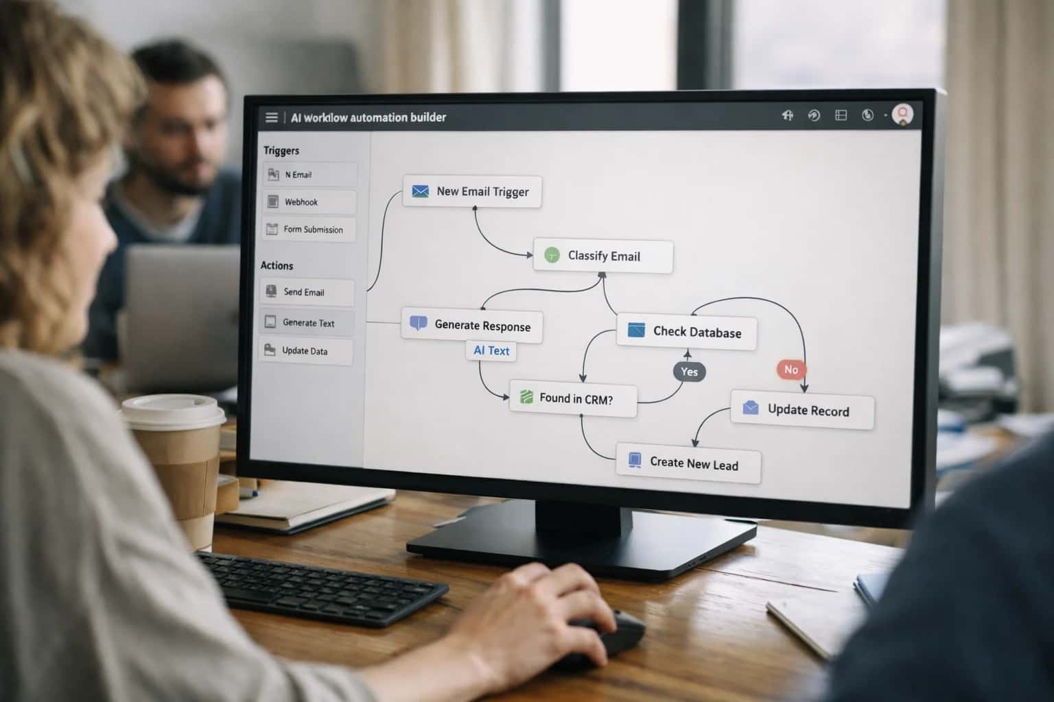
AUTOMATION ARCHITECTURE
Implementing Closed-Loop Process Control with Vision Feedback
This page details the custom workflow architecture that uses real-time vision inspection to automatically adjust upstream manufacturing parameters, creating a self-optimizing production line that maintains quality without operator intervention.
Implementation requires a low-latency integration layer, often built with frameworks like LangGraph or Node-RED, to orchestrate data flow between the vision system (e.g., Cognex, Keyence), the PLC/SCADA network, and the MES. Critical controls include adjustment limits (guardrails), mandatory human-in-the-loop approval gates for significant deviations, and comprehensive observability dashboards to monitor the control loop's performance and stability over time.
CLOSED-LOOP PROCESS CONTROL
Business Impact: Where the Value is Captured
A custom closed-loop workflow turns vision inspection from a passive quality gate into an active process optimizer, capturing value through yield improvement, waste reduction, and operational autonomy.
01
Scrap Cost Reduction & Material Recovery
By detecting and correcting process drift in real-time, the system prevents entire batches of non-conforming product from being produced. This directly reduces raw material waste and the labor cost of rework or disposal. The value is captured in the Bill of Materials (BOM) cost of every unit saved from the scrap bin.
15-25%
Reduction in Scrap Rate
ROI < 12 mo
Payback on Material Savings
02
Throughput Increase via Reduced Unplanned Downtime
Autonomous micro-adjustments to process parameters (e.g., robot path, coating pressure) maintain quality without stopping the line for manual recalibration. This eliminates frequent, short stoppages that cumulatively degrade Overall Equipment Effectiveness (OEE). Value is captured as increased units-per-hour and higher asset utilization.
5-10%
OEE Improvement
0
Operator Stoppages for Drift
03
Labor Leverage & Shift Consistency
The system removes the dependency on highly skilled line operators to visually monitor for drift and manually tweak PLC setpoints. This standardizes process control across all shifts, eliminating human variability. Value is captured by reallocating skilled labor to higher-value tasks like process engineering and exception management.
2-4 hrs/shift
Supervisor Time Reclaimed
100%
Shift-to-Shift Consistency
04
Accelerated Root-Cause Analysis & Mean Time to Repair (MTTR)
Every corrective action is logged with a timestamp, vision snapshot, and the parameter delta applied. This creates a rich, time-synchronized dataset that directly links defects to process states, slashing the time engineers spend correlating data from MES, SCADA, and quality logs. Value is captured in faster resolution of chronic issues.
50-70%
Faster RCA
Defect-to-Parameter
Direct Correlation
05
Risk Mitigation & Recall Avoidance
Continuous, autonomous control acts as a proactive barrier against quality escapes that could lead to customer complaints, warranty claims, or regulatory actions. By maintaining parameters within a tighter tolerance band, the system reduces the statistical probability of a critical defect slipping through final inspection. Value is captured as avoided brand damage and liability cost.
Near-Zero
Critical Escape Risk
PPM
Defect Parts Per Million
06
Energy & Consumable Optimization
In processes like coating, curing, or dispensing, maintaining optimal parameters minimizes over-application of expensive materials (e.g., adhesives, paints) and reduces energy waste from excessive heating or cooling. The closed-loop system enforces this precision continuously. Value is captured directly in reduced utility and material spend per unit.
3-8%
Material Usage Reduction
Sustained
Optimal Setpoint
AUTOMATION ARCHITECTURE FOR SELF-OPTIMIZING PRODUCTION
Implementing Closed-Loop Process Control with Vision Feedback
This page details the custom workflow architecture where real-time vision inspection results are fed back to adjust upstream process parameters, creating a self-correcting production line that maintains quality without operator intervention.
This workflow directly automates the manual, reactive cycle of detecting defects, diagnosing root cause, and adjusting machine settings. It eliminates the scrap produced during the diagnostic lag and the labor spent on constant parameter tuning. The operational upside comes from higher first-pass yield, reduced material waste, and the ability to run at optimal speeds without quality degradation. Implementation requires integrating vision systems with Programmable Logic Controllers (PLCs), SCADA, or machine APIs to form a real-time control loop.
Implementation centers on a low-latency orchestration layer, often built with frameworks like LangGraph, that sits between the vision inference engine and the industrial control network. It must handle data synchronization, enforce guardrails to prevent unsafe adjustments, and maintain a full audit trail. Critical constraints include network reliability, the need for deterministic response times under 100ms, and robust exception routing for scenarios where the recommended adjustment exceeds pre-defined safety limits, requiring human review via an HMI before execution.
CLOSED-LOOP PROCESS CONTROL
Core Workflow Components
A blueprint for a custom automation workflow where real-time vision inspection directly adjusts upstream manufacturing parameters to maintain quality and optimize yield without manual intervention.
01
Real-Time Vision-to-Control Data Pipeline
The workflow ingests high-frame-rate image streams from line-scan or area-scan cameras, processes them through edge-deployed defect detection models (e.g., YOLO, segmentation networks), and extracts critical dimensional or qualitative metrics (e.g., coating thickness variance, weld bead width). These metrics are formatted into low-latency control messages (often via OPC UA or MQTT) and published to a real-time message bus for consumption by the process controller. Latency from image capture to data-ready-for-action must be under 100ms to be effective for high-speed lines.
<100ms
Required Latency
99.9%
Uptime SLA
02
Adaptive Control Logic & PLC/SCADA Integration
A dedicated control agent subscribes to the vision data stream and executes pre-programmed adjustment logic. This logic maps specific defect signatures or dimensional drifts to corrective actions on PLC-set variables—for example, increasing robotic end-effector pressure for a 'gap' defect or modulating a thermal controller's setpoint for a 'curing issue'. The agent integrates directly with PLCs (Siemens, Rockwell) or SCADA historians via industrial protocols, issuing write commands to adjust setpoints. The architecture includes deadbands and rate limiters to prevent system oscillation.
03
Safety & Governance Layer with Human-in-the-Loop
Autonomous control requires robust guardrails. A parallel monitoring agent tracks all adjustment commands against pre-defined operating envelopes; any command exceeding a safe threshold triggers an immediate hold and escalates to a human operator via HMI alert. For continuous improvement, all adjustments are logged with a full audit trail (image, original parameters, command issued, resulting metrics) in a time-series database. Critical adjustments may be routed through a lightweight approval gate in the MES (e.g., SAP ME) during initial pilot phases before full autonomy is granted.
0
Unapproved Overrides
04
Closed-Loop Performance Monitoring & Model Retraining
The system's effectiveness is continuously measured. A dashboard agent correlates adjustment events with downstream inspection results, calculating key metrics like reduction in defect rate post-adjustment and time-to-stabilize. Performance drift in the vision models (e.g., new defect types) is detected automatically. Anomalous images are queued for labeling and fed into a continuous training pipeline, where new model versions are validated on a digital twin of the line before being A/B tested and deployed to edge devices, ensuring the loop becomes more intelligent over time.
25-40%
Defect Rate Reduction
2-4 weeks
Model Retraining Cycle
05
Phased Rollout & Simulation Architecture
Implementation follows a risk-managed, phased approach. First, a digital twin of the production line and control logic is built using tools like NVIDIA Omniverse or custom simulation to test adjustment strategies against historical fault data. The initial pilot runs in 'observer mode', where the system recommends adjustments for operator approval, building trust and refining logic. Finally, control is graduated to 'supervised autonomy' for non-critical parameters, with full closed-loop control reserved for well-understood, high-ROI process variables. Each phase is governed by a rollback plan to manual control.
6-10 weeks
Pilot to Production
06
Business Impact: Scrap Reduction & Throughput Gain
The direct financial upside comes from preventing defective production before it becomes scrap. By correcting process drift in real-time, the workflow reduces the volume of material wasted and the labor for rework or sorting. Secondly, it enables higher line speeds by allowing processes to run at their optimal edge without conservative manual buffers, increasing overall throughput. For a high-volume line, a 30% reduction in scrap rate and a 5% increase in throughput can translate to annual savings in the millions, paying back the custom build investment in a single fiscal year.
30%
Scrap Reduction
5%+
Throughput Gain
A PHASED ARCHITECTURE FOR SELF-OPTIMIZING PRODUCTION
Implementing Closed-Loop Process Control with Vision Feedback
This blueprint details the phased implementation of a custom automation workflow where real-time vision inspection results are fed back to adjust upstream process parameters, creating a self-optimizing production line that maintains quality without operator intervention.
Phase 1 establishes the foundational data loop. High-speed edge vision models inspect products, classifying defects and extracting dimensional metrics. These results are streamed via OPC UA or MQTT to an orchestration layer (e.g., a custom LangGraph application) which logs them against the specific machine and batch ID in the MES. This phase validates data quality, latency (<100ms), and creates the audit trail, de-risking the core integration before any control actions are taken. The focus is on proving measurement reliability and building trust in the signal.
Phase 2 introduces an advisory control layer. The orchestrator analyzes inspection trends against target tolerances, using statistical process control logic. When drift is detected, it generates recommended parameter adjustments (e.g., +5°C curing temp) and routes them to a human supervisor via a dashboard in Ignition or Grafana for review and manual approval. This phase validates the control logic's accuracy in a safe, human-in-the-loop mode, building operational confidence. Phase 3 automates the loop, where approved logic types can trigger direct, secure API calls to PLCs or SCADA systems to adjust setpoints, closing the feedback cycle. Governance gates and rollback switches are mandatory.
CLOSED-LOOP PROCESS CONTROL WITH VISION FEEDBACK
ROI and Operating Economics
Comparison of manual, reactive quality control versus a custom automated workflow that uses real-time vision inspection to adjust upstream process parameters, creating a self-optimizing production line.
| Metric | Manual / Reactive Control | Custom Closed-Loop Workflow |
|---|---|---|
Mean Time to Correct Process Drift | 4-8 hours (next shift review) | Under 2 minutes (real-time feedback) |
Scrap Rate from Chronic Defects | 3.2% of production volume | 0.8% of production volume |
Annualized Cost of Quality (Appraisal + Internal Failure) | $1.8M | $450K |
Production Line OEE (Overall Equipment Effectiveness) | 72% | 89% |
Engineering Hours Spent on Root-Cause Analysis | 120 hours/month | 15 hours/month (exception handling only) |
Latency from Defect Detection to PLC Parameter Adjustment | N/A (manual adjustment) | 150-500 ms (edge-to-PLC loop) |
Audit Trail for Parameter Changes Linked to Defects | Paper logs or disparate MES entries | Automated, timestamped logs in SCADA/Digital Twin |
Preventable Batch Rejects Due to Slow Response | 8-10 per quarter | 0-1 per quarter (critical exceptions only) |
CLOSED-LOOP PROCESS CONTROL
Frequently Asked Questions
Architectural and operational questions for implementing a real-time, vision-driven control loop that adjusts production parameters to maintain quality without manual intervention.
A production-grade implementation embeds a validation layer before any control signal is issued. This includes real-time confidence scoring from the vision model, statistical process control (SPC) checks on the measurement stream, and cross-validation with secondary sensors (e.g., laser gauges) for critical dimensions. Data flagged as low-confidence or anomalous is routed to a human review queue, while the control loop continues using the last known-good parameters or a failsafe default. This prevents garbage-in, garbage-out scenarios that could drive the process out of spec.
Enabling Efficiency, Speed & Accuracy
Intelligent Analysis, Decision & Execution
We build AI systems for teams that need search across company data, workflow automation across tools, or AI features inside products and internal software.
Talk to Us
Search across company data
Give teams answers from docs, tickets, runbooks, and product data with sources and permissions.
Useful when people spend too long searching or get different answers from different systems.
Enterprise searchRAGPermissions
Read more
Automate internal workflows
Use AI to route work, draft outputs, trigger actions, and keep approvals and logs in place.
Useful when repetitive work moves across multiple tools and teams.
AI agentsWorkflow automationGovernance
Read more
Add AI to products and internal tools
Build assistants, guided actions, or decision support into the software your team or customers already use.
Useful when AI needs to be part of the product, not a separate tool.
AI integrationDecision supportModel routing
Read moreARCHITECTURE FOR REGULATED AUTONOMY
Implementing Governance, Controls, and Phased Rollout for Closed-Loop Vision Control
A blueprint for deploying self-optimizing production lines where vision feedback automatically adjusts process parameters, with the governance and rollout sequencing required for safe, auditable operation.
Closed-loop vision control automates the adjustment of upstream parameters—like robot paths, coating thickness, or curing temperature—based on real-time inspection results. The operational upside is direct: it maintains quality spec without operator intervention, reducing scrap and preventing costly deviation batches. Implementation requires tight integration with PLCs/SCADA, with latency budgets under 100ms to affect the next cycle. Governance starts by defining which parameters are auto-adjustable and which require human sign-off, enforced through a rules engine integrated with the MES.
A phased rollout is critical. Start in monitor-only mode, logging proposed adjustments without acting. Phase two introduces adjustments for non-critical parameters in a single cell, with a human-in-the-loop approval gate. Final phases expand to full autonomous control across lines, backed by a digital twin for simulating adjustments before execution. Continuous monitoring tracks adjustment frequency, success rate, and yield impact, with rollback triggers defined for any instability. This controlled approach de-risks the move to autonomous quality control.

About the author
Prasad Kumkar
CEO & MD, Inference Systems
Prasad Kumkar is the CEO & MD of Inference Systems and writes about AI systems architecture, LLM infrastructure, model serving, evaluation, and production deployment. Over 5+ years, he has worked across computer vision models, L5 autonomous vehicle systems, and LLM research, with a focus on taking complex AI ideas into real-world engineering systems.
His work and writing cover AI systems, large language models, AI agents, multimodal systems, autonomous systems, inference optimization, RAG, evaluation, and production AI engineering.
LinkedIn
Limited slotsGet a Free AI Consultation
Partnered with leading AI, data, and software stack.





How We Work
Custom AI workflows for your Business
One-fit-all AI don't work for modern businesses. At Inferensys, we aim to understand your business & custom requirements; which we use to define most efficient agentic workflows, the data, and the tools for your business.
01
Review the use case
We understand the task, the users, and where AI can actually help.
Read more02
Pick the right approach
We define what needs search, automation, or product integration.
Read more03
Build the first useful version
We implement the part that proves the value first.
Read more04
Improve from there
We add the checks and visibility needed to keep it useful.
Read moreThe first call is a practical review of your use case and the right next step.
Talk to Us